
Construction
Both the 63-ft. and 85-ft. boats used the same construction methods, as the designer, Dair Long, essentially scaled the 63-footer up to 85 ft. The Navy carved the hull number (C-***) into several structural members—such as the keelson and stem—in addition to painting it on each vessel
The Army, however, did not carve the number into the hull. Instead, it relied solely on painted hull numbers, which has made tracking these vessels in later years more difficult. The reasons for this difference are unclear, though they may reflect variations in procedure or experience.
In addition, all U.S. Army and Navy small craft carried an identification plaque, typically about 4”×6”, located in or near the pilothouse. This plate listed the vessel type or model, hull number, year launched, design number, manufacturer, and the branch of service for which the boat was built. The Army also installed a Bakelite (an early plastic) plate in the engine room. Plate designs varied not only between manufacturers but sometimes even within a single manufacturer’s production.
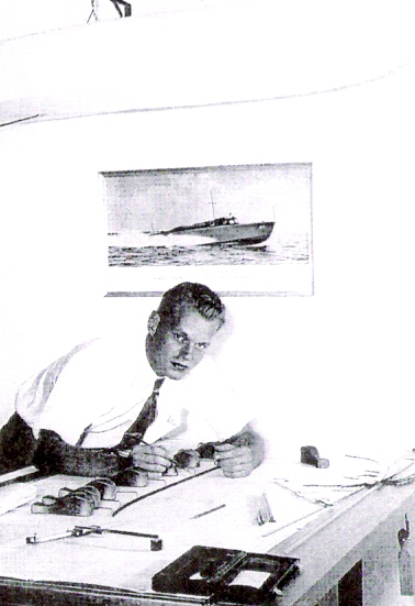
File:63 ft\2019-06-12\Dair
The stem, keel and chines were made of Honduras mahogany double-rabbeted to receive the inner and outer planking individually. The stem, knee, forefoot and two keel sections were scarfed and bolted. The chines were made up in three pieces and scarfs were located between the keel scarfs. The structural watertight bulkheads were hollow, being built up of two layers of 1/4-inch fir plywood separated by 1-3/8-inch spruce stiffeners. The bulkheads were attached to the keel and chines with metal angle clips. The transom stiffeners and boundary framing were made of Honduras mahogany. After the keel, bulkheads, molds between the bulkheads and transom were set up, spruce stringers, spaced one foot apart, were fastened into notches provided in the bottom and sides of the bulkheads and clamped to the temporary molds. These stringers were effectively the “ribbands” of a normal building form except that they became a permanent part of the boat. Steam-bent white oak transverse frames, 1-1/8-inch X 1-3/8-inch were placed inside and outside of the stringers. Intercostal tiller blocks of spruce were fitted and screwed in place through the oak frames making each frame an “I-section.”.” The intersections of frames and stringers were then through bolted. A shelf and clamp of spruce were then fitted and fastened at the sheer. Knees and gussets of 3/8-inch fir plywood were fitted and screw fastened to both sides of the frames at the sheer and chine.
Before the boat was planked, the engine beds, which were prefabricated built-up box girders with oak runners, plywood sides and internal vertical and diagonal spruce bracing, were slipped into place through the transom framing and bolted though each frame. Together with the keel and chines, the engine beds formed the main strength members of the bottom of the boat.
File: 63 ft\construction series
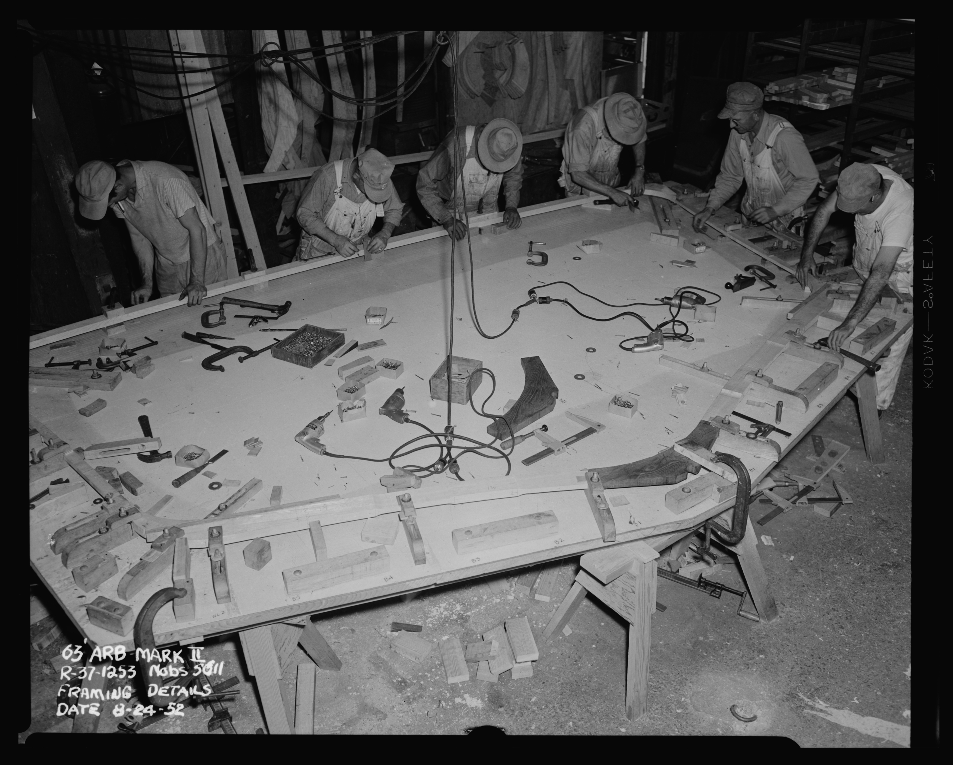
Rib Layout and Assembly
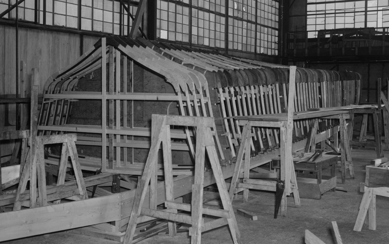
Stacking Ribs on a Jig
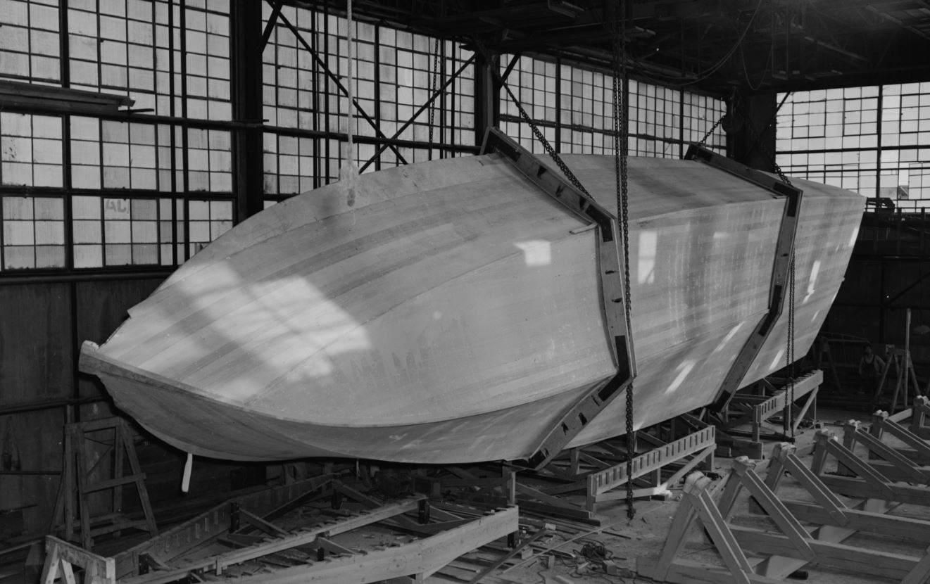
Flipping Hull Before Interior Work
The boat was double planked and had eight-ounce cotton duck laid in marine/aviation glue between the two layers of planking. The inner planking, which was cedar, 1/2-inch thick on the bottom and 7/16-inch on the sides, ran at 45 degrees diagonally. The shipwrights screwed the inner planking to the keel, chines, and sheer clamp, then fastened it to the frames by means of copper nails. The outer planking of Honduras mahogany, was ¾-inch thick on the bottom and 9/16-inch thick on the sides, and ran longitudinally. The outer planking fastened through the inner planking into the frames with bronze wood screws. The inner planking fastened to the outer planking with wood screws between the frames from the inside. They nailed the 3/4-inch fir plywood decking with Monel anchor-fast nails to the 1-3/8-inch spruce deck beams, and screw fastened it to the shelf and clamp. The seams and butts were bolted on seam straps and butt blocks. The plywood was then covered with 12-once canvas, laid in white lead paste-paint. The deckhouse structure was made of 3/4-inch fir plywood with mahogany trim.
The electrical system was a 24 volt DC system that ran off the four, six volt batteries supplied for each engine. The system could be supplied with 110 volt AC shore power from a receptacle on the port side of the bridge and fed through a rectifier before charging the batteries. The lighting system used standard marine fixtures with gasketed glass enclosures with additional wire mesh guards in the engine room.
For much more layout and construction detail, as well as photos, see the book Crash Boats, by Dave Linley & Terry Holtham, as well as the Manuals & Publications section of this site.
85' & 63' Crash Boat Specifications
| Description | 85 Ft. Model 379 | 63 Ft. Model 168 | 63 Ft. Model 314 | 63 Ft. Model 416 |
|---|---|---|---|---|
| Production Run | 140 | 16 | 352 | 79*** |
| Length Overall | 85' 0" | 63' 0" | 63' 0" | 63' 0" |
| Length at Waterline | 78' 10" | 58' 10" | 58' 10" | 58' 10" |
| Max (Over Guards) Beam | 20' 3" | 15' 6" | 15' 4" | 15' 4" |
| Beam at Waterline | 18' 8" | 13' 10" | 13' 10" | 13' 10" |
| Depth Amidships | 11' 2" | 8' 9" | 8' 9" | 8' 9" |
| Draft (Propeller Tips) | 4' 8" | 3' 10" | 4' 0" | 4' 0" |
| Displacement, Light | 70,000 lbs. | 37,000 lbs. | 38,000 lbs. | 38,000 lbs. |
| Displacement, Full Load | 103,712 lbs. | 50,500 lbs. | 51,500 lbs. | 51,500 lbs. |
| Fuel Capacity | 3840 gal. / 4 tanks | 2000 gal. / 3 tanks | 1580 gal. / 2 tanks | 1580 gal. / 2 tanks |
| Octane Rating | 87-100* | 87-91 | 87-91 | 87-91 |
| Lube Oil | 70 gal. / 2 tanks | 70 gal. / 2 tanks | 50 gal. / 2 tanks | 50 gal. / 2 tanks |
| Frash Water | 500 gal. | 150 gal. | 150 gal. | 150 gal. |
| Complement (Officers/Petty Officers/Crew) | 2, 2, 9 | 2, 2, 4 | 2, 2, 4 | 2, 2, 4 |
| Max Speed at Full Load | 34.75k / 40mph | 48k / 55 mph | 31.5k / 36.2 mph | 31.5k / 36.2 mph |
| Max Continuous Speed at Full Load | 24.3k / 28 mph | 40k / 46 mph | 25k / 29 mph | 25k / 29 mph |
| Fuel Consumption, Max Cont. Speed | 140 gal/hr. | 140 gal/hr. (my guess) | 90 gal/hr. | 90 gal/hr. |
| Range, Statute Miles (85 Ft. Main/Cruise) | 644/6035 | 550 (my guess) | 475/530 | 475/530 |
| Engines | 2 Packard | 2 Packard | 2 Hall-Scott | 2 Hall-Scott |
| Engine Model, all are V-12 | 4M-2500 | 4M-2500 | Defender | Defender |
| C.I.D. Each | 2490 | 2490 | 1996 | 1996 |
| Total BHP | 2500-3600 | 2500-3000 | 1300-1400** | 1300-1400** |
| Propeller Diameter (3 Blades) | 32"**** | 23" | 23.75" | 23.75" |
| Propeller Pitch (2" Monel Prop Shaft) | 34"**** | 23.25" | 23.75 | 23.75 |
- *Ratings range 87-130
- ** Some sources rate the supercharged Hall-Scott Defender engines at 950 bhp ea, 1990 total hp
- *** An additional 60 of the Model 314 boats were transferred to the AAF
- **** The June 1944 issue oof Pacific Motor Boat describes the shafts as 2.5" diameter, spinning 31X32 two bladed props custom designed by Dair Long but that did not become the standard propeller